Advertisements
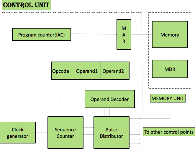
Control unit

Control Unit is the most complex unit.
Main functions
-
Fetching instructions
-
Analyzing the op code
-
Generating control signals for performing various micro operations
Hardware resources:
Hardware circuit in conventional hardwired control units are
- Instruction register (IR)
- Program Counter or Instruction address counter (IAC)
- Clock generator
- Pulse sequencer
- Pulse distributor
- Operation code decoder
- Program status word (PSW) register
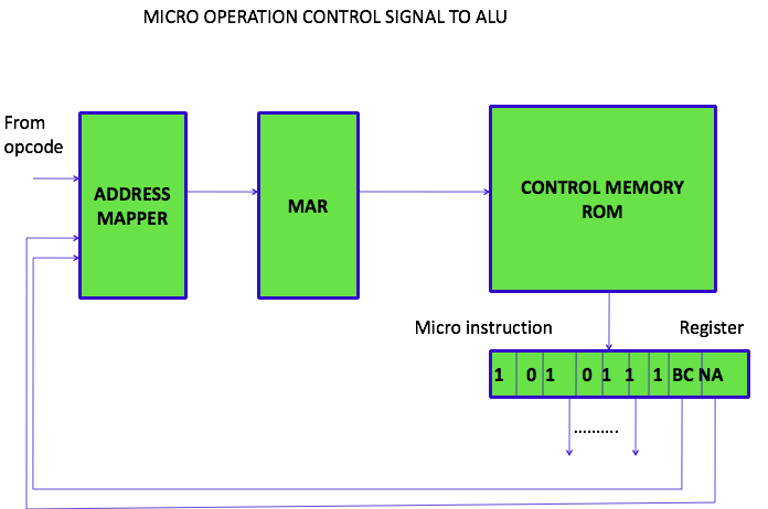
In micro programmed control unit,
Instead of code decoder & pulse distributor, the additional units are
- control memory
- control memory address register
- micro instruction register
IAC
- Instruction address counter
- contains memory address of next instruction to be fetched
- When an inst fetched, IAC++ & points to address of next instruction.
Instruction fetched form memory is transferred to instruction register(IR)
Every instruction contains
- Opcode
- Operand
- Operand address
- Register address
- Constant
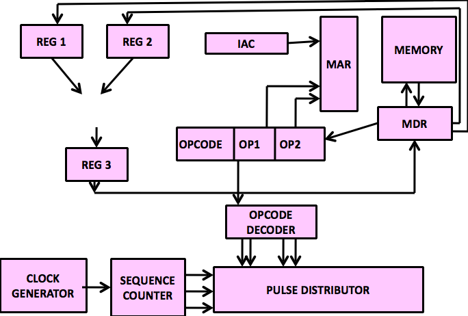
In a hardwired control unit,
opcode decoder -> opcode is analysed
has 1 output line for each instruction
output line for corresponding instruction becomes active

Clock generator :
- generates continuous sequence of clock pulses
Pulse Sequencer
- using clock signal generates timing states
- Instruction is broken to 4/5 steps
- Each timing state corresponds to steps in an instruction cycle.
Pulse distributor ( 2 inputs are)
- Timing Pulses
- Output lines from opcode decoder.
Pulse distributor generates micro operation pulses in sequence with appropriate delay.
PSW
- Interrupt Enable flag
- Over flow flag
Micro operations for Subtract Instruction
| No. | Control Point Activated | Micro-operations performed | Remarks |
| 1 | IAC -> MAR | Contents of IAC are transferred to MAR | Address of next Instruction is placed in MAR |
| 2 | Memory Read | Contents of the location pointed by MAR are transferred to MDR | Instruction is now available in MDR |
| 3A | MDR -> IR | Contents of MDR are transferred to IR |
Instruction fetched is placed in IR |
| 3B | IAC + 1 -> IAC | Contents of IAC are incremented |
IAC is incremented by 1 ao that it points to the next instruction |
| 4 | Opcode field -> Opcode decoder | Contents of opcode field in IR are sent to opcode decoder input. |
The opcode decoder decodes the OPCODE and activates the corresponding output line. Here sub output line is activated. |
| 5 | Operand I -> MAR field | Contents from first operand field are transferred to MAR. |
The address of the first operand to be fetched is placed in MAR. |
| 6 | Memory Read | Contents from the location pointed by MAR are transferred to MDR. |
First operand is now available in MDR. |
| 7 | MDR -> R1 | Contents of MDR are transferred to R1. | Inputs to ALU are given through registers R1 and R2. Therefore, first operand is placed in R1. |
| 8 | Operand II -> MAR field | Contents from the second operand field are transferred to MAR. | Second operand address is placed in MAR |
| 9 | Memory Read | Contents of Memory location are transferred to MDR. | Now second operand is available in MDR. |
| 10 | MDR -> R2 | Contents from MDR are transferred to R2 | Second operand is placed in the other input in ALU. |
| 11 | R2 -> R2 | Contents of R2 are complemented. | For subraction 2's complement method is used. Hence the second operand is complemented. |
| 12 | ADD | Contents of R1 and R2 are added. | Addition is performed. |
| 13 | ALU -> R3 | The result is transferred to R3. | R3 is the output register of ALU. |
| 14 | R3 -> MDR | The contents of R3 are transferred to MDR | The result is stored in memory. So it is placed in MDR. |
| 15 | Operand I -> MAR field | Contents of first operand field are transferred to MAR | Usually the result is store in one of the operand' addresses. Here it is the first operand address. |
| 16 | Memory Write | Contents of MDR are stored in memory. | The result is stored in the first operand address. The first operand is lost. |