Advertisements
Magnetic Storage Devices


Purpose of using tape drive
- Backup unit – take copies of disk contents
- Transport files from one site to another conveniently
- But CD with large capacity, high reliability, easy portability & flash ROM
Basic Principle
- Magnetic medium causes magnetization by passing current through a coil in read/write head.
- Head is stationary & media moves during R/W.
Standard format for recording on magnetic disk
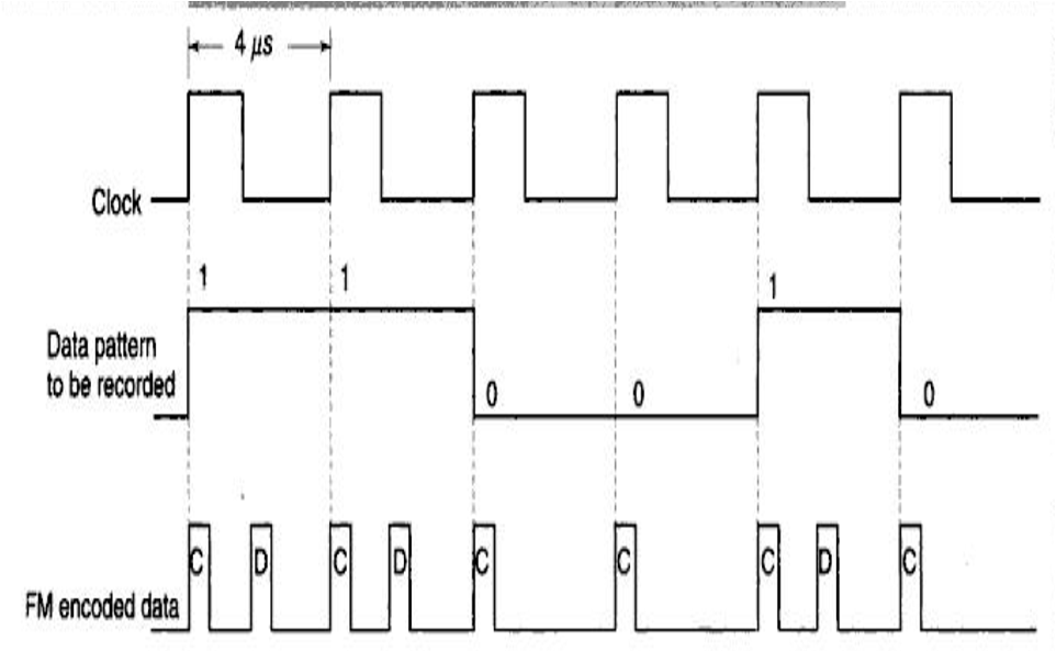
Frequency Modulation (FM)
- Single density format
- Clock pulse written at beginning of each bit
- Data pulse at center
- 1 – Data pulse present
- 0 – Data pulse absent
- Each bit cell is of 4 micro sec for floppy disk
- Two flux changes per bit
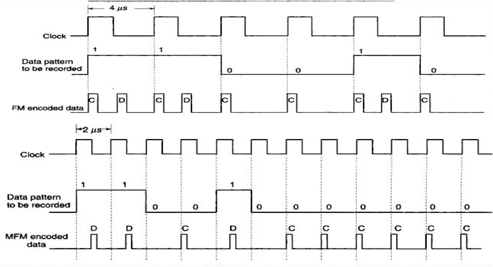
Modified Frequency Modulation (MFM)
-
Double density format
-
No Clock pulse at beginning
|
Data Pulse |
Meaning |
|
1 |
No clock pulse, data pulse at centre |
|
0 following 1 |
Neither clock not data |
|
0 following 0 |
Clock pulse written at beginning & no data pulse |
- Each bit cell is of 2 micro sec for floppy disk
- So, disk capacity doubled
- Only one flux change (since, no clock pulse)
%20.png?alt=media&token=3f865103-d7dc-4e25-8a72-96e44e601ca3)
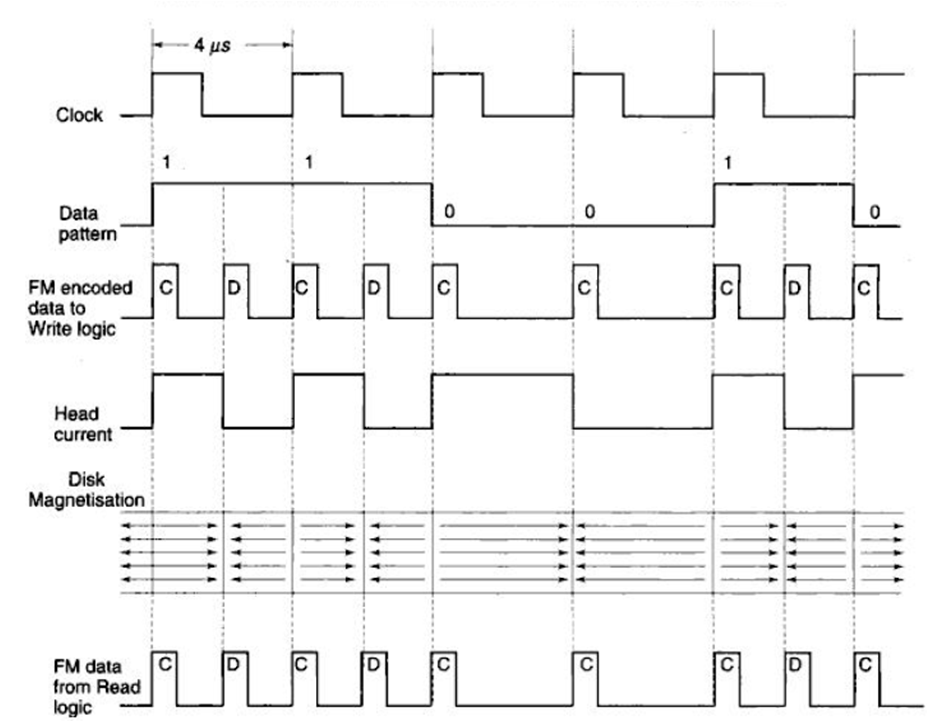
Recording on magnetic medium
- Info stored in flux reversals on medium
- not in amplitude / direction of magnetization
- Each data bit is recorded in form of flux change
Head configuration
- R/W head – core with air gap & set of coils
- For writing data on medium:
- Data converted into current
- Passed through R/W Head coils
- Current generates magnetic field (flux) in air gap

- Current direction controlled to produce opposite polarity mag fields
- Series of flux reversals on medium
- During reading, when flux transition pass under head gap, voltage introduced in R/W coils
- Voltage converted into data pulses
- Magnetization due to current in head during write operation & induced emf in head during read operation
Recording on magnetic medium
Disk Drive Types
1. Hard disk drive (HDD)
- Medium is rigid circular platter – disk
2. Floppy Disk Drive (FDD)
- Medium is flexible circular diskette
Both surfaces, top & bottom can be used for storing data
HDD provides better performance, cos,
- Higher capacity of data storage
- Faster access time of data
- Higher data transfer rate
- Better reliability of operations
- Less data errors or data loss
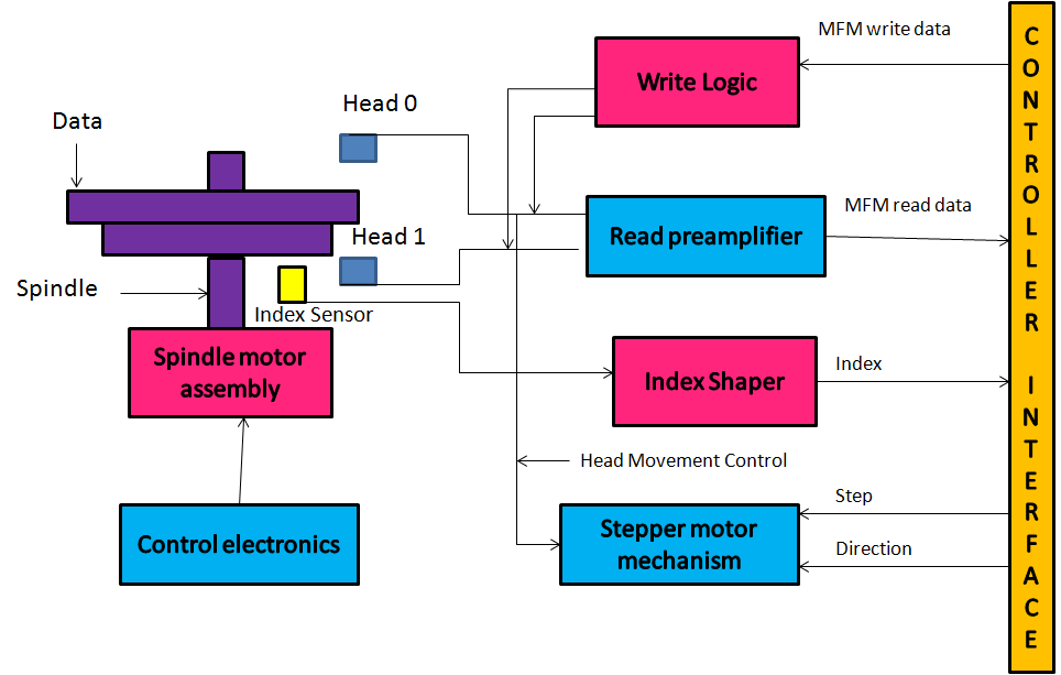
Disk Drive Block Diagram
Interfacing Hard disk drives - ST 506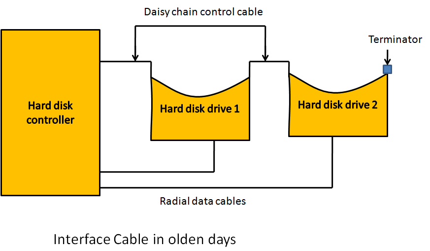
Interfacing floppy disk drives - ST 506

Common Concepts between FDD & HDD
- Data is written bit by bit on disk
- Clock bit is also written on medium
- Data recorded on concentric circular tracks
- Disk rotates at fixed speed
- Moving head positioned on desired track by positioning mechanism
Comparison/difference between FDD and HDD
|
FDD |
HDD |
|
Head touches media – on R/W |
Does not touch – flying height |
|
Max 2 R/W head (:2 surface) |
Multiple R/W head (many platters on single spindle) |
|
Head Positioning Mechanism: Uses stepper motor |
Head Positioning Mechanism: Uses: Stepper motor (open-loop disk drive) Voice Coil Servo Mechanism (closed loop disk drive) |
|
Diskette rotation in low speed 300 rpm or 360 rpm |
High speed 2400rpm, 3600rpm or 7200rpm |
|
Lesser no. of tracks – 40/80 Track density – 48/96 TPI |
No. depends on hard disk size – 14”, 18”, 51/4” , 31/2”, etc. |
|
Low recording density (DPI) |
High since rotates fast |
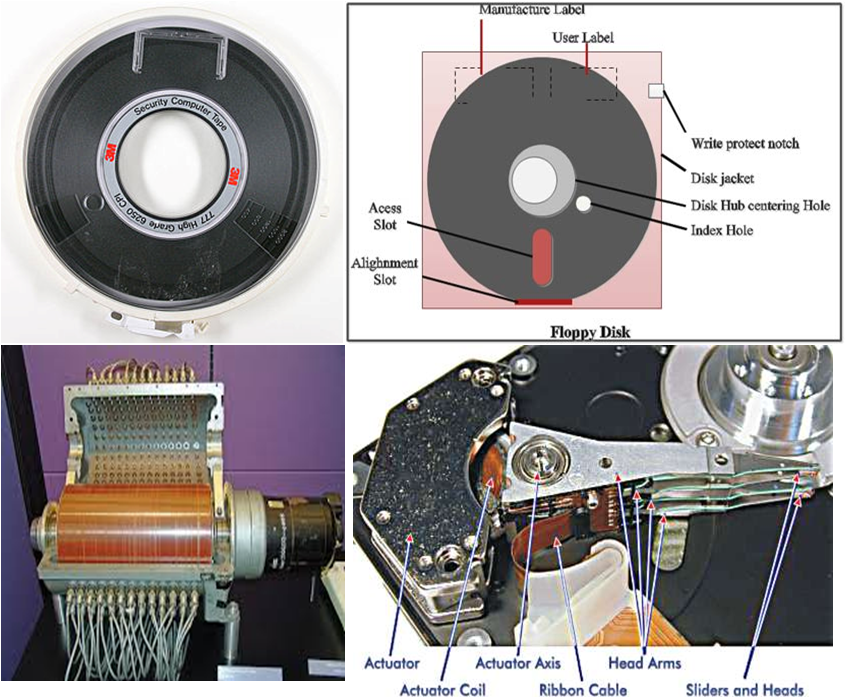
Floppy Diskette
- Ultra thin plastic (Mylar) Piece in circular shape
- Thickness – few thousand of an inch
- Coated with magnetic material enclosed in protective jacket
- Oval access hole on jacket – provide contact b/n R/W head & diskette.
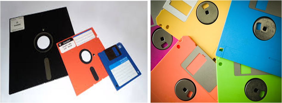
Sizes of Diskettes
1. 8 inch disk
- Old standard diskette
- Now Obsolete
2. 51/4 inch disk – Mini-floppy
- Widely used recent computer – PC, PC-XT, PC-AT
- Vinyl cover to protect disk surface
3. 31/2 inch disk – Micro floppy
- New industry standard diskette
- has rigid plastic cover with metal/plastic slide – protect disk when not in use
Single sided disk
- Earlier floppy diskettes
- Only one side of diskette was used to store info
Double sided disk
- Currently manufactured
- Both sides of diskette are used for storing info
- Diskette Classification
- Single density diskette
- Double density diskette
- Uses MFM to store info. Stores twice amount of info that stored on single density diskette of same size.
Components
Track
- Diskette –logically divided to fixed no. of tracks-Concentric circles
- Reading/Writing only on specified tracks & not in between.
|
Inch of diskette |
No. of tracks |
|
8 |
77 |
|
51/4 double density |
40 |
|
51/4 high density |
80 |
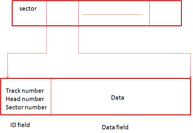
Sectors
- Tracks divided into no. of sectors
- depends on size & recording method used
- Fixed no. of data bytes are written, like, 128,256,512 or 1024

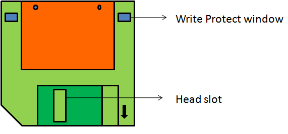
Head
- Read/Write heads are mounted on common assembly in FDD.
- Head Moves to & fro between outermost & inner mot track in both (forward & backward) direction.
- Tracks are sequentially numbered, starting from outermost track as track 0.
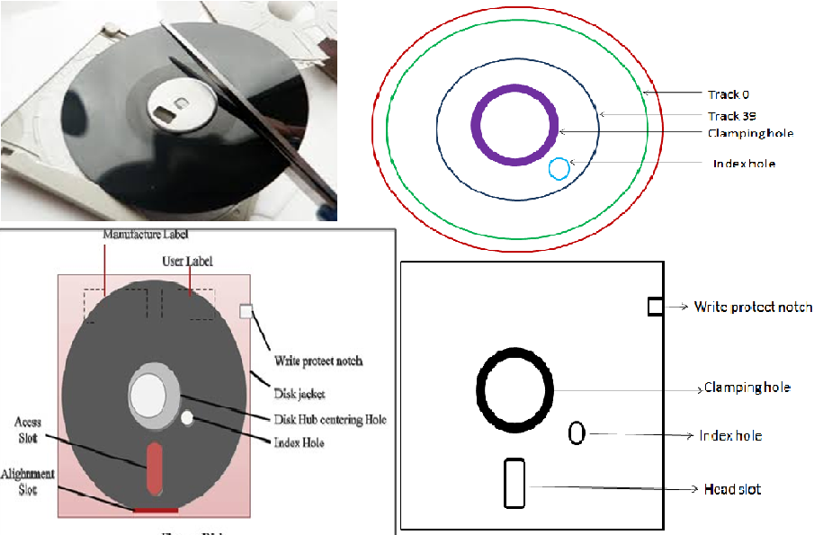
Index hole
- Small hole punched on diskette near center
- Indicates the beginning of track
- Initial writing on any track is only after sensing index hole
- Index sensor senses the index hole once on each revolution
Write protect feature
Allows to read & Denies to write attempt
1. Technique 1:
- In 51/4” disk – small notch punched at outer edge of jacket – Write Protect notch
- If notch opened – Permit writing
- If notch closed – Deny writing
2. Technique 2:
- In 31/2” disk, write-protect window with plastic tab to open /close
- Write Protection provided when window is opened
Classification based on sector organization
Hard Sectoring
- No. of Sectors on each track is physically fixed on manufacturing
- Beginning identified by sector hole punched on plastic disk
Soft Sectoring
- No. of Sectors per track is chosen by software – varies
- No physical hole for sector information
|
Hard sector |
Soft sector |
|
Fixed sector size |
Sector size chosen by software |
|
Obsolete |
Currently used |
|
Several standards, differing in like no. of sectors per track, no. of data bytes per sec & length of gaps on diskette |
Floppy disk format
Widely used – IBM system 34 & IBM 3740
Each track has many fields having specific bit patterns & gaps for
- data field
- synchronization
- error detection & identification

Data recording
- Data is written bit by bit on track
- Read/Write heads use electro magnetic recording techs
- One head on top & another on bottom surface
- Write operation – WRITE DATA line carries Clock & Data Pulse
- Write circuits pass current to R/W head – flux transition
- Read – produce emf on diskette rotation
- Pre-amplifier circuits in FDD amplifies shape pulse
Need for writing clock pulses in diskette
- If data bits – 0 – no flux transition
- While reading, will appear there is no data
- Clock bits differentiate between no data & zero data